COMMERCIAL
3220: Non-Insulated Ribbed Steel Doors
20 Gauge
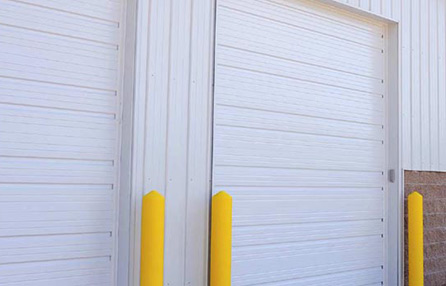
C.H.I.’s ribbed steel doors offer a traditional and time-tested design that will provide you years of reliable and worry-free use. When your project calls for a door that provides dependability and stands up under the rigors of daily use, choose from our line of non-insulated ribbed steel doors in a variety of gauges and product features.
.
OVERVIEW
Model 3220 pan ribbed steel doors have a variety of features to meet your design and performance requirements.
Section Construction:
- 2″ thick pan sections
- 20 gauge steel exterior
- Ribbed Panel Profile (2 horizontal ribs with alternating “v” grooves)
Size:
- Max standard size 24’2” wide x 16′ high
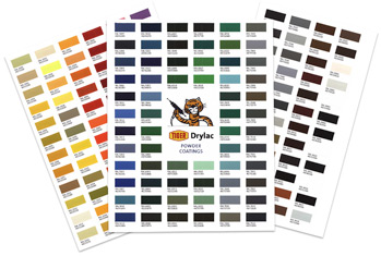
Colors / Appearance:
- White
- Stock RAL powder-coat option in 188 colors
- Various accessories and options available
**R-Values have been calculated in accordance with ASTM C518 standards
SECTIONS
SECTION CONSTRUCTION:
- Roll-formed sections are 20-gauge 2″ thick, hot-dipped galvanized with a baked-on polyester finish
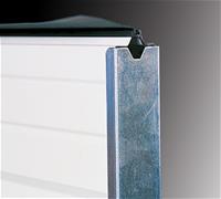
- Box shaped stiles are riveted to the face of the section and are galvanized for additional corrosion protection
- Tongue and groove meeting rails provide superior rail strength and weather resistance
- Panel Profile: 2 horizontal ribs with alternating “V” grooves
-
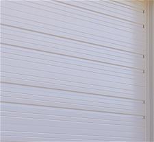
20-gauge ribbed steel panel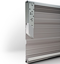
Ribbed Insulation Detail
Polystyrene Insulation with
Vinyl Backer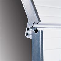
Tongue & Groove meeting rails
seal out the elements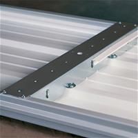
Box-shaped stiles provide added
rigidity and section strengthMAXIMUM STANDARD SIZE:
- Max width 24’2” x 16’ high (Contact Factory for larger sizes)
Colors / Finish:

White
Panel Configurations:
- 21″ or 24″ high by width of door
TRACK
Track Configuration:
- Tracks are 2′ or 3′, as specified
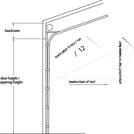
- 12″ radius, 15″ radius
- Normal Headroom, Low Headroom, Vertical Lift, High Lift, Incline
- 20″ & 32″ radius (2″ track & up to 10′ high doors only)
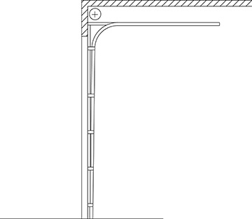
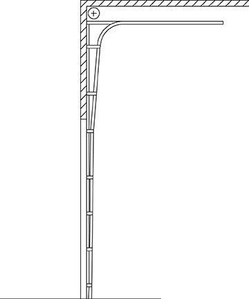
Normal Headroom / Standard Lift View>>
Low Headroom: Front Mount View>>
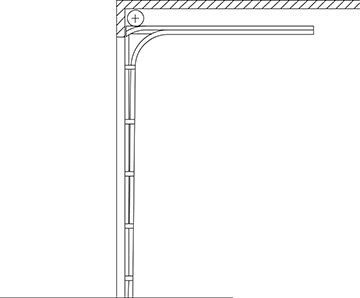
Low Headroom: Rear Mount View>>
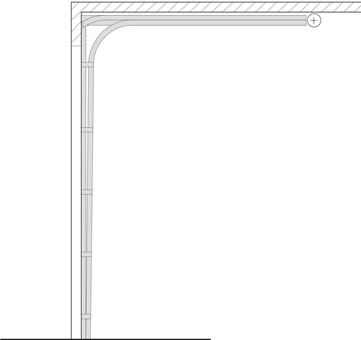
Vertical Lift View>>
High Lift View>>
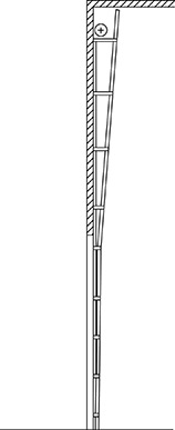
Incline View>>
Mounting Options:
- Bracket Mount (leg out), Clip Angle Track, Continuous Angle Track
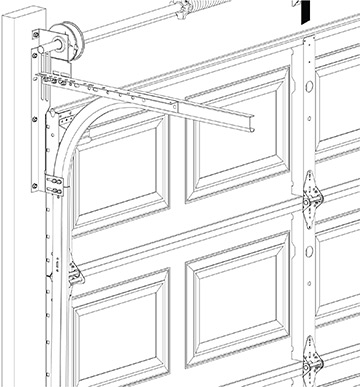
Bracket Mount View>>
Clip Angle Track View>>
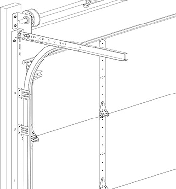
Continuous Angle Track View>>
 Reverse Angle Mount View>>Available for Clip Angle & Continuous Angle Track
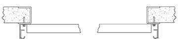
Track Gauge:
- 2″ Tracks – up to 8′-0″ high = 17 gauge roll-formed galvanized steel
- 2″ Tracks – 8′-0″ 10′-0″ = 16 gauge
- 2″ Tracks – over 10′-0″ = 14 gauge
- 3″ Tracks – 12 gauge
HARDWARE
Hinges:
11-gauge or 14-gauge hinges, as specified
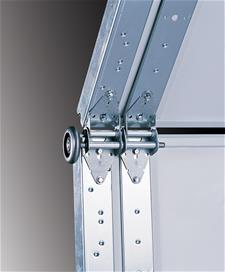
Rollers:
- 2″ or 3″ long-stem or short-stem steel ball bearings rollers

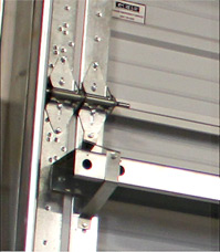
Brackets:
- Top fixtures (min. 12 gauge)
- Bottom fixtures (min. 13 gauge)
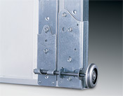
Single or Double Edge Endstiles:
OPERATION
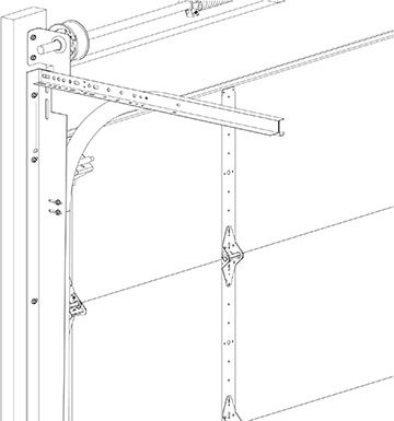
Counterbalance System (Springs)
- Oil tempered torsion springs are mounted on a cross-header shaft supported by galvanized steel ball breaking end plates and center bracket(s)
- Springs are calculated for exact door weight, size and trajectory in accordance with ANSI 102 standards for a minimum of 10,000 cycles
NOTE: May be specified for higher cycles when available - Counterbalance is transferred through galvanized aircraft quality cables secured to bottom of the door
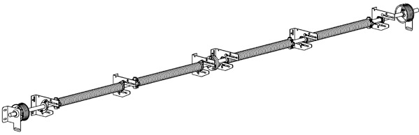
Above, Torsion/Spring Assembly with Four Spring Layout, Standard Headroom
Operation:
- Manual Operation
- Motor Operation: Trolley or Jackshaft
- Chain Hoist Operation
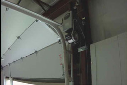
Jackshaft Operation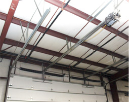
LITES
Optional Lites / Windows
- 24″ x 6″, 24″ x 12″, or 34″x 16″ lites with 1″ insulated glass (Clear, Tempered or Tinted)
- Optional Aluminum Full View Frame to match size and panel layout of steel section
(Optional open for field glazing, 1/8″ DSB, 1/8″ polycarbonate, 1/8″ tempered glass, 1/4″ tempered glass, 1/2″ insulated glass or 1/2″ tempered insulated) - Special glass options available. Contact factory for details.
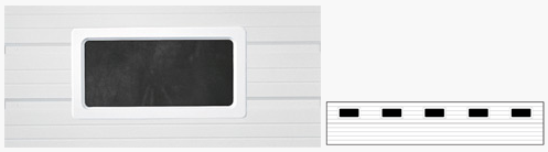
24″ x 12″ (shown is 24″ section height)
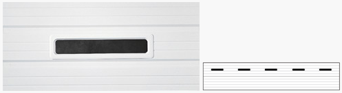
24″ x 6″ (shown is 24″ section height)
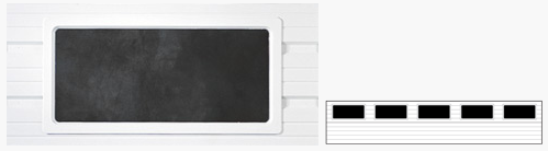
34″ x 16″ (shown is 24″ section height)

OPTIONAL ACCESSORIES
Doors are available with a variety of Specialty Options for specific installation needs. Contact Factory for additional options.
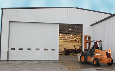
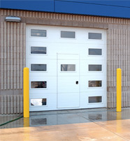
Swing-Up Sectional PostA perfect answer for openings that are too large for a single overhead door that must accommodate large machinery or equipment on an infrequent basis. Operating on a single pivot point that is designed to swing left or right, it allows the use of one (1) smaller door for everyday requirements and the full opening when needed. See video.
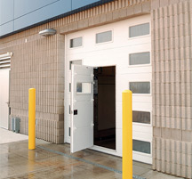
Pass Doors Whether it’s for convenience or necessity, there are circumstances where a pass-through door is requested to provide ingress and egress in an overhead door enclosed opening without having to open the overhead door. C.H.I. can accommodate this need with a state-of-the-art design pass-door option. Available in our urethane core models 3216 and 3212, it’s the ideal choice to solve this need.
Header & Jamb Seals Seal the perimeter of the opening to provide additional air infiltration and thermal protection.
CERTIFIED WINDLOAD
Wind can be unpredictable and destructive. This is why C.H.I. Windbreaker Series and iSeries doors are designed, tested, and built to the most rugged specifications. Wind chamber tested to ensure windload resistance, these extra-sturdy designs provide enhanced defense against the elements.
C.H.I. Overhead Doors developed the resilient Windbreaker Series garage doors to protect against high wind conditions. The super-resilient C.H.I. iSeries Impact Approved doors have strength designed to withstand direct collision of projectiles and other windborne debris at high speeds.

Additional Windload Information:
Navigating the complex windload codes and compliances can be a daunting task. C.H.I. sales associated and distributors are able to help you understand the specific codes governing your geographic area. For additional information, these websites offer a great deal of information.
![]()
Technical Data Sheets:
- TDS #168 – Wind Loads on Garage Doors – FAQ
- TDS #177 – Application of Kd Factor To Garage Door Wind Load Determination Using ASCE 7
- TDS #178 -Garage Door Wind Load Determination – Effective Wind Area
- TDS #180 – Wind Load Ratings for Non-Tested Garage Door and Rolling Door Sizes
- TDS #181 -General Code Inspection Guidelines For Wind Load Rated Garage Doors

SPECS / DRAWINGS
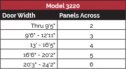
Door Width/Panels Across Chart
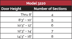
Door Height/Panels Across Chart
Track Resources
Standard Lift Doors
Low Headroom: Front Mount
Low Headroom: Rear Mount
High Lift Doors
Vertical Lift Doors
Reverse Angle Track: Leg In (Steel Jambs Shown)
Bracket Mounted Track Angle Mounted Track: Leg out (Wood Jambs Shown)